
Voltage-Controlled Filter (VCF) – Voltage-Controlled Amplifier (VCA) – Waveforms
Voltage-Controlled Filter (VCF)
The voltage-controlled filter is a major part of subtractive synthesis. There are many different ways to design a filter, and although they basically do the same thing, they all sound a little bit different. The filter is the part of the synthesizer that is most responsible for shaping the tones you get out of it, and it gives each synth its own character and unique sound.
In general, filters block some things while letting other things through. A filter in a synthesizer is no different; it blocks some frequencies while letting others through. There are several different types of filters you can choose from depending on which frequencies you need to block/pass to achieve your desired sound.
Low-Pass: Removes frequencies above the cutoff frequency. Makes waves sound darker or muddier.
High-Pass: Removes frequencies below the cutoff frequency. Makes waves sound brighter.
Band-Pass: Let’s a narrow band of frequencies centered around the cutoff frequency through.
Notch / Band-Reject: Removes a narrow band of frequencies centered around the cutoff frequency.
Filter Types (Modes)
A low pass filter passes (allows) frequencies below a certain point known as the cutoff frequency. Frequencies above the cutoff frequency are blocked. This filter lets you cut the high-end out of your signal or get rid of harmonics.
")
Low pass filter sweep
A bandpass filter passes frequencies around the cutoff frequency but blocks the ones above and below it. It only allows a narrow band of frequencies through. It is useful if you are trying to highlight a certain frequency.
")
Bandpass filter sweep
A high pass filter passes frequencies above the cutoff frequencies and blocks the ones below it. It lets you cut the low end out of your signal or only allow harmonics through.
")
High pass filter sweep
A notch filter blocks the frequencies around the cutoff frequency and lets all others pass. This can come in handy if you have one particular frequency you want to block (maybe it’s causing feedback or just sounds bad).
")
Different synths or filter modules may have one or more than one type of filters in them. Sometimes they’re all available at the same time from different jacks, and sometimes you can switch between them using a switch or a knob.
Cutoff Frequency
The above descriptions are just generalizations; signals aren’t usually completely passed or blocked on either side of the cutoff frequency. The gain actually starts curving down then dropping steadily. Let’s take a look at a low pass filter as an example:

Note that the cutoff frequency isn’t the point where the filter starts affecting the gain. It’s the point where the gain is -3dB (half).
The cutoff frequency can be adjusted on almost all VCFs with a knob or a control voltage. This is where you can start using your filter to create more dynamic sounds. Maybe you patch a low pass filter so that the cutoff is fairly high when you first play a note, then it drops down as the note is held. This gives you a note that is bright when it is first hit and gets more dull over time, just like many acoustic instruments do when they are played.
Slope
The rate at which the gain drops after the knee at the cutoff frequency is known as the slope of the filter. As you’re shopping for a filter, you will see slope specs like 12dB/octave or 24dB/octave. This means that every time the frequency doubles (goes up an octave), the gain drops 12dB or 24dB respectively. Sometimes the slope is described in “poles”, with each pole equaling 6dB. A 2-pole filter would have a slope of 12dB/octave, a 4-pole filter would have a slope of 24dB/octave, etc.
6dB isn’t a very steep slope for a filter. You can use it to brighten or muddy up your sound, but it doesn’t really cut any frequencies to the point where you can’t hear them. The tone knobs on your old stereo probably have a 6dB slope.
12dB will filter out most of the sound, but you’ll still be able to hear some of it.
24dB is pretty steep. You can use a 4 pole filter to cut unwanted frequencies to the point where you won’t notice them.
Resonance
Turning up the resonance knob (or increasing the control voltage) on your filter boosts the frequencies right around the cutoff frequency. It also tends to attenuate the lower frequencies (some filters compensate for this so you don’t lose your low end as you crank up the resonance). The width of the peak where the frequencies are boosted is called “Q”.

As you continue to turn up the resonance, the sound will start to ring a bit right around the resonant frequency. If you turn up the resonance even more (if your filter will let you; some won’t) then the filter will start to self-oscillate and you’ll find a sine wave at the output. The peak is so tall and narrow that very little of your input signal will be coming through. If your filter is calibrated so that it tracks with your keyboard then you can use it as a sine wave VCO.
Note: While they can be used in this way, VCFs don’t make very good replacements for VCOs. Oscillators are very sensitive to changes in temperature, and a true VCO has extra circuitry to compensate for this and make it more stable. VCFs don’t, so they’re not very good at staying in tune. On some of them you can drastically change their pitch just by blowing on their circuit boards.
Let’s take a look at an actual VCF. This is the Filtare SEIII by Division 6. It’s a Eurorack filter that is designed to sound like the SSM2040 filter chip, which is no longer in production. It is a 4 pole filter, so its slope is 24dB/octave.
It has 4 different filter types, and they each have their own separate output jack.
The notch output is a little unique in that it has a “balance” control that lets you shift between all low pass and all high pass. When set in the middle, it passes both low and high frequencies with a dip (notch) in the middle.
All the controls on this filter can either be controlled by a knob or by an external control voltage.
There are two CV inputs for the cutoff frequency. One has a level knob so you can adjust how much the incoming voltage affects the frequency. The other is a fixed 1 volt per octave, making it easy to use this filter as a sine wave oscillator if you want (there’s also a trim pot on the back so you can tune it).

Voltage-Controlled Amplifier (VCA)
") A VCA, or Voltage-Controlled Amplifier, lets you use a voltage to control the amount of another signal that is allowed through to the output of the module. The higher the control voltage, the more signal is passed. At some voltage level, the entire signal is let through.
A VCA, or Voltage-Controlled Amplifier, lets you use a voltage to control the amount of another signal that is allowed through to the output of the module. The higher the control voltage, the more signal is passed. At some voltage level, the entire signal is let through.
Note: Most VCAs could be more accurately called “Voltage-Controlled Attenuators” as they reduce the signal level (depending on the input CV), but they don’t usually amplify it.
When the control voltage is 0V (or below), no signal is passed and the output is silent.
VCAs have quite a few uses:
Volume Control
You can use your VCA to turn just about anything into a volume control. Run your audio signal through it, then connect the CV input to a mod wheel, foot pedal, or any voltage source you want.
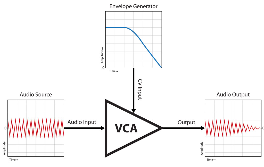
Envelope Shaping
One of the most common uses of a VCA is envelope shaping. Think about when you hit a key on a piano; the amplitude starts out pretty loud, then over time it fades away. If you let go of the key then the volume drops off pretty quickly. You can use a VCA in conjunction with an envelope generator to achieve the same effect with notes on your synthesizer.
An envelope generator (EG) is a module or circuit that generates a voltage that is triggered by something and changes over time (don’t worry, we’ll talk more about them later). If you’re trying to mimic a piano, you can configure the EG so that it is triggered by a key being pressed on your keyboard, it sends out a strong voltage at first, then it fades down to 0 over time.
The voltage sent out by the EG matches the way you want your amplitude to change over time. Connect the output of the EG into the CV input of your VCA and it will cause the amplitude of your note to fade out like a piano note.
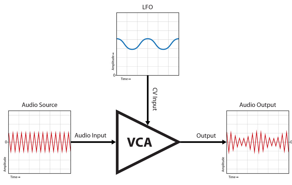
Tremolo
Mix a slow sine wave with some DC (to make sure the whole wave stays above 0), then feed them into the CV input of your VCA. The audio signal will mostly come through to the output because of the DC bias, but you will hear the amplitude get louder and quieter in time with the sine wave you are using to modulate it. This effect is called tremolo.
Amplitude Modulation
Tremolo uses a slow (3Hz, for instance) wave to modulate the amplitude of your audio signal, so you can actually hear the resulting loud/quiet cycles. If you increase the modulating frequency so that it gets up into the audio range, however, things start to get interesting. The modulation is so fast that you are now changing the shape of the original audio signal’s waveform, and new frequencies appear.
To illustrate how AM works, let’s hook an actual VCA to an oscilloscope and see what happens.
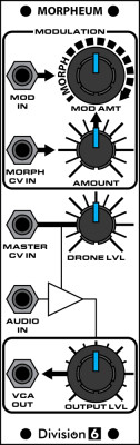
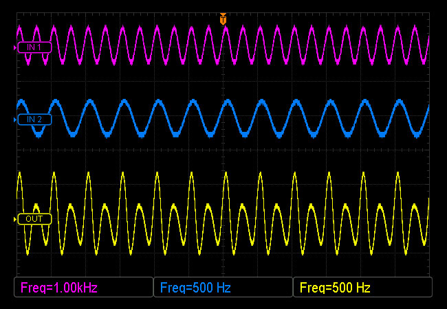
We’ll feed a bipolar (swings above and below 0V) 1kHz sine wave into the AUDIO IN jack; this is called the carrier. Next, let’s run a 500Hz sine wave into the MASTER CV IN jack; this is called the modulator. We’ll mix a DC offset voltage with the 500Hz wave so it is unipolar (the whole thing sits above 0V). Here’s what the input waves look like:
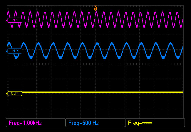
As we turn up the OUTPUT LVL control, a wave starts forming on the output. The farther above 0 volts wave 2 (the modulator) is at any given time, the more of wave 1 (the carrier) gets let through. Since the resulting output wave is created by an interaction between two different waves, it is going to be something other than a sine.
Remember from our lesson on harmonics that any signal other than a pure sine wave is going to have some frequencies other than the fundamental frequency in it? It so happens that the frequencies produced by amplitude-modulating one waveform with another have a very specific relationship. Take a look at this spectrum showing the frequencies contained in the output wave of our experiment:
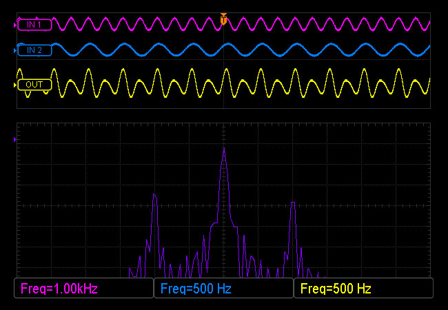
In the middle you can see the original carrier signal. There are also two smaller spikes above and below the carrier frequency. These are called sidebands, and they represent the sum and difference between the carrier and the modulator frequencies. The frequency of the upper sideband is equal to the frequency of the carrier plus that of the modulator. The frequency of the lower sideband is the frequency of the carrier minus that of the modulator.
- Upper sideband: Frequency= carrier+modulator
- Lower sideband: Frequency= carrier-modulator
Let’s use the scope’s cursors to take some measurements to see if this holds true.
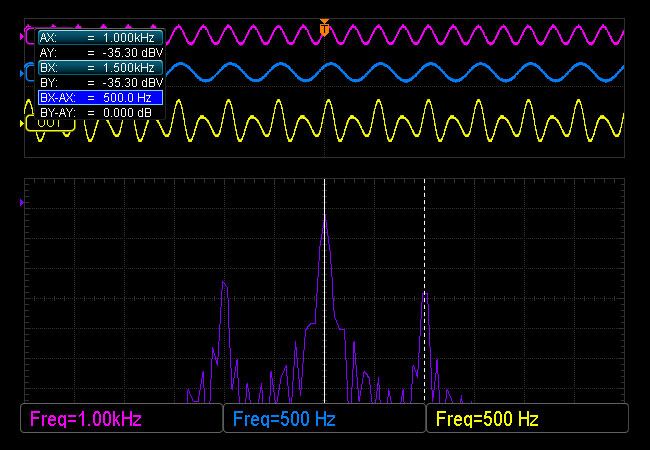
Cursor A is lined up with the big spike in the middle. Notice how it’s sitting right at 1kHz, which is the frequency of our carrier.
Cursor B is lined up with the upper sideband. It’s frequency is 1.5kHz, which is equal to the carrier’s 1kHz + the modulator’s 500Hz. You can also see in the blue highlighted text in the upper left that the difference between the two spikes is 500Hz. We don’t even need to use the cursors to see that the lower sideband is 500Hz below the carrier.
If you change one of the input frequencies, you change the relationship between the carrier and modulator and the sidebands appear at different locations. If you’re listening to the signal as you change the frequency, it can sound like the pitch is going up and down at the same time because the sidebands are moving in different directions (toward or away from the carrier).
Now you know how amplitude modulation adds brand-new frequencies to your signal that weren’t in either of the original waves. The sideband frequencies that get generated are quite often not musically related to each other, so AM tend to make things sound a bit dissonant, often metallic or “gongy”.
Waveforms
 What we perceive as sound is air pressure changing over time. In electronics, sound is represented as a signal that changes over time (AC waveform). Speakers are used to convert these electrical signals into changes in sound pressure that we can actually hear.
The shape of the waveform (how the voltage changes over time) determines what the signal actually sounds like, or its timbre. A simple tone can sound soft, smooth, harsh, buzzy, like a beep, like a bell, etc. depending on its shape. The shapes can get really complex and even be completely random, but here are a few basic ones that actually have names. You can see what they look like and click to hear them.
Sine Wave

You may remember this one from the last chapter. It goes up, slows down as it reaches the top, switches directions, then accelerates down below 0. It slows down as it reaches the bottom, switches directions and accelerates back up.
Square Wave

This wave is basically positive for half a cycle, then negative for half a cycle.
Triangle Wave

This wave goes up until it hits the top, then instantly switches directions and heads toward the bottom. Once it hits the bottom it instantly reverses and heads back to the top. There is no acceleration and deceleration as in a sine wave.
Sawtooth / Ramp Wave

The signal starts at the bottom and works its way to the top. Once there, it immediately drops back to the bottom and starts over again. A sawtooth can also be flipped around so that it starts at the top and works its way down.
The terms “sawtooth” and “ramp” are fairly interchangeable. Some people call one a sawtooth and the reversed version a ramp, but there isn’t much consistency in which is called which.
Noise

This isn’t really a repeating waveform, but a random signal.
There are a few other properties of a waveform that affect how it sounds.
Amplitude

This is basically how “big” the signal is, or how far above and below the 0 line it swings. The larger the amplitude, the louder the sound.
In the above picture, the second waveform has twice the amplitude of the first waveform.
Frequency

The faster the signal changes, the higher pitch it sounds. Frequency is usually measured in Hertz (Hz), which basically means cycles per second. If one were to double the frequency of a tone, it would sound 1 octave higher. For instance, a 440Hz tone in musical terms is known as note A. An 880Hz tone would also be an A, but one octave higher.
In the above picture, the second waveform is twice the frequency of the first one.
Harmonics
 Different waveforms sound different. A sine wave sounds different than a square wave, which sounds different than the waveform that comes out of an accordion. All these waves have unique timbres because they have different harmonic content.
A harmonic is basically a multiple of a fundamental frequency. For example, let’s say you’re playing a note with a frequency of 100Hz. That would be the 1st harmonic.
: 100Hz")
The 2nd harmonic would be twice that frequency, or 200Hz.

The 3rd harmonic would be 3 times the fundamental, or 300Hz.

You can see that it’s pretty easy to figure out the 4th, 5th 6th, etc.
Now let’s do some frequency analysis of our different waveforms to see why they sound the way they do.
We’ll start with the sine wave:

In the spectrum analyzer display above, the horizontal axis (x) is the frequency and the vertical axis (y) is level. What it’s telling us is how much energy the signal has at various frequencies. In the case of our sine wave, you can see that there is a single spike right at 100Hz. That’s pretty much what we expect to see since it’s a 100Hz tone.
Now let’s look at a sawtooth:

Notice that the sawtooth not only gives us a spike at the fundamental frequency, there are also some smaller spikes at each harmonic frequency going up (200Hz, 300Hz, 400Hz, etc.) The triangle wave contains the fundamental and a whole series of harmonics, which explains why it sounds so much different than a sine wave.
Now let’s check out a triangle wave:

Once again we have several spikes, but this time they’re only at the odd-numbered harmonics (3rd=300Hz, 5th=500Hz, etc.).
Here’s what a square wave looks like:

Like the triangle wave, the square wave contains odd harmonics, but they fall off less rapidly as the frequency increases.
Waveforms tend not to contain even harmonics if they are vertically symmetrical. The square and triangle waves above are perfectly mirrored above and below the horizontal center line, so they don’t have any even harmonics. The sawtooth, on the other hand, is lopsided and does contain even harmonics. This rule of thumb applies to other waveforms too.
Why do different waveforms contain different frequencies, even though they’re basically just a single frequency? Let’s explore that. Remember our sine wave? It only contained its fundamental frequency with no additional harmonics. A sine wave is a pure tone and can be used as a basic building block to create other wave shapes. You can get just about any waveform you want by adding a series of sine waves at the correct frequency, amplitude and phase.